It’s been quite a while from the last post. I’ve had many projects and several ideas that would have made for a nice blog post but I never quite got around to writing, but now I finally decided to write a small memo.
When you are using a LCD the driver needs to generate bias voltages for the voltage forms that the segments are driven with. For example the Brother display uses has generates the bias voltages from a single voltage. This is then turned into multiple voltages with a resistor string and a quad opamp that buffers the voltages. In this blog post I showed a charge pump that is used to generate the negative voltage that the display requires. The bias voltage then sets the contrast of the display, so a proper bias voltage is needed so that the on the screen screen is readable, and there is a contrast potentiometer on the front of the Brother display that sets the maximum bias voltage.
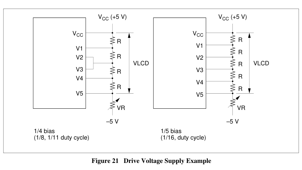
The Brother display required a negative rail of almost -20V, but this is not that common in my experience nowadays. A common type of relatively cheap LCDs for simple (hobby) projects are the HD44780 compatible alphanumeric screens. This can be found in many colors and sizes. The bias voltages for these controllers work in a similar fashion, and you can find a resistor string in the display modules that generates the required voltages from the pins.

HD44780U datasheetIn most 5V applications the bottom voltage is actually derived from potentiometer dividing voltage between 5V and 0V, and we require no negative voltage at all.
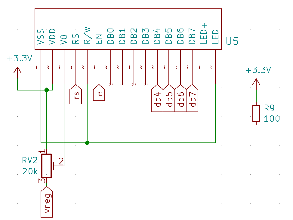
But now there arises a problem: if we use a 3.3V digital supply (or even lower, HD44780 datasheet specifies that VCC should be in the range 2.7V–5.5V) we’re going to be in trouble with the contrast of the screen. At the same time, we often can’t increase the supply voltage, since for example most 32-bit microcontrollers can’t be ran at a higher voltage. Of course, we can have some voltage level translation from 3.3V to 5V so that we can run the display at 5V, but that just adds many components and we still need a separate 5V supply rail.

HD44780 display modulesNow, 3.3V might still make for a dimly readable contrast on the smaller 8×2 and 16×2 character displays, but the result isn’t that good. And with a larger 20×4 display there won’t be much of anything to see even if the V0 contrast pin is at zero volts.
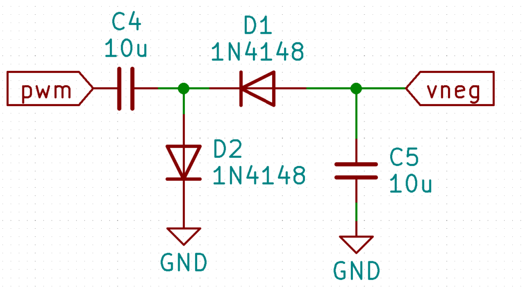
But there is a nifty way to generate a small negative voltage from a single PWM pin from a microcontroller. And it isn’t usually that hard to find a free PWM pin in any case since a microcontroller is most likely driving the display module in any case.
You need just two diodes and two capacitors to make a simple charge pump that inverts the voltage (minus two diode drops). If you have for example two diodes in a single SOT23 package that’s only a total of three additional components. Then just put some squarewave in and you’re done!

The charge pump can easily be driven from a microcontroller pin since the LCD bias doesn’t need much current, and likewise the frequency isn’t that critical since small variations in the voltage doesn’t really matter. And of course, using Schottky diodes will increase (or should I say decrease?) the generated voltage.
This circuit can even be easily added as a quick hack after you have manufactured PCBs and realize that the you are running the display from 3.3 volts but didn’t realize that how poor contrast it results in (yeah, I’m speaking from experience.)